Laboratorio M1K Analog Devices: Amplificador a Transistor Emissor Comum
Laboratório: Amplificador a Transistor Emissor Comum
Este laboratório foi baseado no material disponibilizado pela Analog Devices, fabricante do módulo educacional M1K Analog Devices: [1]
Objetivos
Montar, testar e analisar o circuito de amplificador a transistor emissor comum. O amplificador foi projetado com ganho 5 e é capaz de alimentar uma carga de 1 KΩ com um sinal senoidal de 2 Vpp e acoplamento AC.
O experimento permitirá observar o sinal senoidal de entrada (vin) e o sinal senoidal de saída (vout) acrescido do ganho de amplificação.
Equipamento e Materiais
- Modulo Analog Devices M1K e software Pixelpulse
- Componentes Eletrônicos:
- Resistores: 10 KΩ, 47 KΩ, 100 KΩ, 470 KΩ, 1 k KΩ, 1,5 K KΩ e 6,8 K KΩ
- Capacitores: 47 uF e 22o uF
- Transistor NPN 2N3904
Procedimentos Práticos
- Usando a matriz de contatos e fios, monte o circuito amplificador emissor comum, usando o transistor 2N3904, como ilustrado na figura:
 [1]
[1] - Configure o módulo Analog Devices M1K para Gerar Voltagem/Medir Corrente no canal A e Medir Voltagem no canal B.
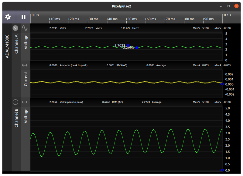
- Configure o canal A para gerar um sinal senoidal variando entre 2,3 V e 2,7 V e frequência de 100 Hz.
- Observe no canal B a a forma de onda senoidal da voltagem sobre a carga de 1 KΩ oscilando +/- 1 V em torno da tensão base de 2,5 V e com defasagem de 180 graus em relação ao sinal de entrada. A onda senoidal está em torno de 2,5 V devido a referência da carga ter sido colocada nesta tensão.
- Remova o sinal de entrada e meça as tensões DC na base, emissor e coletor do transistor. Estas foram as tensões de projeto do amplificador.
- Analise o projeto do circuito e verifique os valores calculados em função dos valores práticos medidos.
- Análise dos dados
- Gráficos das entradas e saídas do amplificador e cálculos teóricos.
Cálculos:
Vb
Ib = n order to estimate the base current, we can estimate the emitter current as (1 V - 0.7 V)/57 Ω ≈ 5.3 mA. Using β = 200 for the transistor, the base current can be estimated to be approximately 5.3 mA/200 = 26.5 μA. This current flows through the parallel combination of the two base bias resistors, so the voltage drop due to base current can be estimated to be (26.5 μA)(6.8 KΩ||1.7 KΩ) ≈ 36 mV. The base voltage, accounting for base current, can now be estimated to be 1 V - 36 mV ≈ 0.96 V. Note that this slightly changes the collector current, which slightly changes the base current, so technically these calculations are iterative, but one iteration is generally sufficient. The emitter current can now be estimated as (0.96 V - 0.7 V)/57 Ω ≈ 4.6 mA. From this example we can see how a small change in base voltage can significantly change the emitter current, and hence collector current, when the emitter voltage is small. We require small base and emitter voltages since we are operating on a relatively low supply voltage of 5 V and need to keep the collector-base junction reverse-biased over the full collector voltage swing. The next step is to estimate the collector bias voltage as 5 V - (4.6 mA)(470 Ω) ≈ 2.8 V. In order to get our required output swing of +/-1 V across the load resistor we will need about +/-1.47 V at the collector to compensate for the amplifier output resistance of 470 Ω being loaded by the 1 KΩ load. This means that the collector voltage will swing between 1.33 V and 4.27 V, which keeps the collector-base voltage reverse-biased and provides sufficient margin to the supply voltage. Note that since we have a reasonably large output swing and are fairly close to the dynamic range limits, we will incur some possibly visible distortion in the output waveform.
Fundamentos sobre Transistores
Observações e Conclusões
Referências
Evandro.cantu (discussão) 09h49min de 7 de julho de 2020 (-03)
